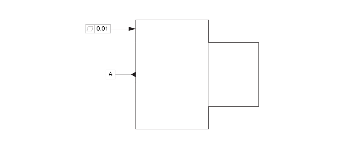
FLATNESS (FLAT NESS)
DEFINITION: ALL THE POINTS ON A SURFACE ARE IN ONE PLANE, THE TOLERANCE SPECIFIED BY A ZONE FORMED BY TWO PARALLEL PLANES. LIKE STRAIGHTNESS, FLATNESS IS REFERENCED TO ITSELF AND SO IS APPLIED WITHOUT NEED FOR OR REFERENCE TO A DATUM.
If flatness control continues to allude you, then like that of circularity control, an in-depth investigation into its root cause would be the next appropriate step. By asking ourselves “where to begin?”, we are led to reviewing the evidence at hand, and that would be the scrap parts themselves.
By visually understand what its defective shape looks like, then we can begin to theorize as to the cause of this shape. Here again, we can look to the effect, to speculate as to what caused this. Let’s consider a few of the more typical shapes and the possible causes:
- If the face of a round part looked like that of a three lobed potato chip, we might begin by speculating that the workholding or even tool pressure might have contributed to this. This is especially the case when a 3-jaw chuck is being used.
- If the face was convex (or concaved), we might question the alignment of the machine or program (i.e., taper).
- If after evaluating several parts we observe a randomness in the shapes and orientation of the same, then there might be reason to consider stress relieving and the processes leading up to this operation.
LET’S TAKE A CLOSER LOOK AT THE FIRST SCENARIO ABOVE
If the part does resemble that of a three lobed potato chip, we next need to determine how this shape came to exist. How could a part that was turned on a lathe come to have alternating high and low surfaces? The answer simply is that the cutting tool removed more material from some of this surface than from others. We are now led to question how this would have come about and there are two likely explanations.
- Assuming the part is thin walled, we could theorize that the three jaws properly supported the part every 120° while the balance of the part was unsupported. This would have permitted the tool to push the part surface backward between the jaws, leading to an uneven depth of cust and explain the shape.
- Another possibility is that the grip force in conjunction with “jaw lift” distorted the part and presented this now distorted potato chip shape to the cutting tool. Upon unclamping the part, the relaxed part will now reflect this same potato chip shape.
- The last consideration is that caused exclusively by pull back chucks and can be described as being the exact opposite of point #2 above. With every pull back chuck used, a separate stationary part stop is utilized to pull the work piece back against. It is this pull back motion/force that can bend the part back over this surface that simply changes the high surface presented to the cutting insert, but the outcome is the same.
WHERE DOES THIS LEAVE US?
Since there are quite a few contributors for flatness error, resist the tendency to guess at the cause. Even worse, to throw money at it. Let’s list here the most probable causes:
- Workholding
- Tool pressure
- Machine condition (i.e., alignment, backlash, etc.)
- Surface finish
- Stress relieving
- Thermal growth (work piece)
- Part rigidity (A subset of the above)
If “flatness” continues to cost your company money, and you are looking to resolve the matter more quickly, contact us to review the details of your application. Depending on what is known/unknown about the root cause, we might recommend a scoping program that includes root cause analysis, written report and action plan.

