Learn More About the ABC’S of Chucks and Workholding:
- Types of Chucks
- Spindle Data Sheet
- Grip Force
- Maintenance

For Safe Operation
- SWITCH OFF power before setting, inspecting, lubricating or changing the chuck. Danger by catching of operator in a machine.
- Never operate selector valve and solenoid valve during spindle rotation. Danger by discharge of clamped workpiece during spindle rotation.
- Do not exceed recommended speed of chuck related with Max permissible input force. (See page 13, 14.) Danger by discharge of chuck or workpiece.
- Never start the machine with door open. Work or jaw may discharge with door open.
- Do not exceed MAX. permissible input force related with plunger input force. (See page 13, 18.) Danger by discharge of chuck or workpiece.
- In cases of power failure Kitagawa cylinders are fitted with check valves and pressure release valves. When power is restored the solenoid valve resumes its normal function. Gripped workpiece may discharge by lighting or interruption.
- Secure clamp bolts with specified torque. (See page 20.) Danger by discharge of chuck or workpiece in case of damaging of chuck.
- Do not forget to grease chuck! (See page 33.) Danger by discharge of workpiece related with lowering gripping force caused by insufficient lubrication.
- The height of the jaw should be within the maximum gripping force limits. (See page 15, 18.) Danger by discharge of chuck or workpiece in case of damaging of chuck.
- When chucking components internally reduce the hydraulic pressure by more than 50%. Danger by discharge of chuck or workpiece in case of damaging of chuck.
- When machining a long workpiece, support it with a center, tailstock or steady rest. Danger by discharge of workpiece, if it is too long.
- Do not attempt to modify chuck. Danger by discharge of chuck or workpiece in case of damaging of chuck.
- Never attempt to operate a machine while under the influence of alcohol or drugs.
- Gloves and ties should not be worn when operating a machine.
- When lifting chuck, use eyebolt or lifting belt. Danger by dropping.
- When gripping workpiece, make sure your hand is out of gripping area. Danger or finger broken or cut.
- Never hammer chuck, jaws or gripped workpiece. (See page 30.) Danger by discharge of chuck or workpiece in case of damaging of chuck.
Mounting Steps of Chuck
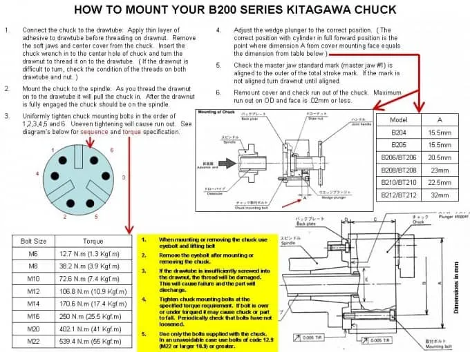
Connect the drawtube to the cylinder.
Screw the drawtube into the cylinder piston rod with the rod retracted as far as it will go. (If it is tightened at the intermediate position, the locking pin of the piston may be damaged.)
Mount the cylinder to the spindle (cylinder adapter).
Check that the run-out of cylinder is minimized before routing the hydraulic piping. Move the piston at low pressure (0.4MPa, 0.5MPa, 4 5kg f/cm) two or three times and set the piston at the forward end before switching power off.
CAUTIONWhen mounting or removing the chuck, lift it with the crane, using an eyebolt or lifting belt. (For a chuck of 8 inches or less, the eyebolt is not attached.) Be sure to remove the eyebolt from the chuck after mounting or removing.Connect the chuck to the drawtube.
Remove the soft jaw and cover of the chuck to insert the connecting handle into the central hole of the chuck. Connect the chuck onto the drawtube, turning the drawnut. (See Fig. 7.) If the connecting of the chuck and drawtube is difficult, check the thread. If connected by force,the plunger will be damaged, thus resulting in poor accuracy.
WARNINGIf the drawtube is insufficiently screwed into the drawnut, the thread will be damaged, thus eliminating the gripping force momentarily. It will result in danger due to discharge of workpiece.Mount the chuck to the spindle (back plate).
Turn the joint handle so that the chuck is properly attached to the spindle mounting face of lathe.Uniformly tighten chuck mounting bolts in the order of 1, 2, 3, 4, 5, and 6 as shown in Fig. 8. (Uneven tightening will cause run-out. For specified torque of mounting bolts, refer to page 20.)
WARNINGTighten chuck mounting bolts at the specified tightening torque. If the tightening torque is insufficient or too strong, bolts will be damaged and the chuck or workpiece may fail. Periodically check that bolts are not loosened. Use only attached Kitigawa brand bolts. In an unavoidable case, use bolt with strength code 12.9 (M22 or more: 10.9) or more and sufficient length.Adjust the wedge plunger to the correct position.
The adequate wedge plunger position at the cylinder advance end is where dimension A fromcover mounting face is shown in the following table. (See Fig. 7.) At this time, check the master jaw standard mark is aligned to the outer line of total stroke mark. (See Fig. 14.) Since the clip stop (locking system) is provided to the drawnut, adjust the nut where it is effectual.
Remount the cover and check run-out of the chuck.
Make peripheral run-out and face run-out of the chuck to 0.02mm or less.
CAUTIONFor the cylinder, refer to the Instruction Manual.

Maintenance and Inspection of Chuck
WARNING
To maintain the chuck for a long period of time, it is necessary to lubricate the chuck on a regular basis. Inadequate lubrication causes malfunction at low hydraulic pressure, reduces gripping force and affects gripping accuracy, and causes wear and seizure. Consequently, securely lubricate the chuck.
After machining, clean the chuck body and slideway with air gun, etc.
Use rust prevention coolant oil so that rust does not reduce gripping force.
| Section to be lubricated | Grease used | Lubrication cycle |
| Apply grease from the grease nipple at the periphery and of each master jaw with a grease gun. | CHUCK-EEZ Grease or Chuck Grease Pro | Once a day. However, when the machine is operated at high speed rotation or a large amount of water soluble cutting oil is used, more of lubrication is needed according to service conditions. |
CAUTION
Disassemble and clean the chuck at least once per 6 months or every 100,000th used (once every 2 months for the casting). See if parts are worn or racked and replace if required.
Lubricate the chuck before reassembling.
After assembling, confirm the gripping force is specified force with the procedure P-12.
Disassembling Steps
For safety, use the lifting belt or eye bolt and fix the chuck.
(1) Loosen jaw mounting bolts to remove the soft jaws and T nuts.
(2) Remove the cover.
(3) Loosening chuck mounting bolts, turn the drawnut with the connecting handle to remove the chuck.
(4) Remove the wedge plunger toward rear chuck.
(5) Move the master jaws to center and remove them toward rear chuck.
Coat recommended grease before assembling the chuck. At this time, do not mistake the numbers marked on the body, master jaws and wedge plunger.
Troubleshooting of Chuck
If the chuck malfunctions, stop the lathe and try the following countermeasures.
| Problem | Possible Reasons | Countermeasures |
| Chuck will not operate | The inside of the chuck is broken. | Disassemble and replace part. |
| Slideway seizes. | Disassemble and repair damaged part with oil stone or replace it. | |
| Hydraulic cylinder is not operating. | Check that pressure reduction valve, change over valve and horse system are correct. | |
| Insufficient master jaw strokes | Too much swarf in chuck. | Disassemble and clean. |
| Drawtube is loose. | Remove and retighten it. | |
| Workpiece slippage | Insufficient master jaw stroke. | Position master jaw so that it is in stroke center when workpiece is gripped. |
| Insufficient clamping force. | Check that hydraulic pressure adequately set. | |
| Formed dia. of top jaw does not match workpiece dia. | Reform top jaw according to correct method. | |
| Cutting force is too high. | Calculate cutting force and reduce it up to chuck specifications. | |
| Insufficient lubrication on master jaws and each slideway. | Lubricate from grease nipple and grip and grip again jaws without workpiece in chuck. | |
| Speed is too high. Whirling is found by mis-alignment such as work feeder, steady rest, tailstock, etc. | Reduce speed up to necessary gripping force. Secure alignment to eliminate whirling. | |
| Poor accuracy | Periphery of chuck is run out. | Tighten chuck bolts correctly. |
| Foreign matter is caught in serrations between master and top jaws. | Remove top jaw and clean serrations thoroughly. | |
| Top jaw mounting bolts are inadequately tightened. | Tighten bolts to correct torque. | |
| Forming of top jaw is inadequate. | Check that forming plug is parallel to chuck and face and plug is not deformed due to gripping force.Also, check hydraulic pressure while forming and face roughness. | |
| Top jaw is deformed and top jaw bolts are extended because top jaw is too high. | Reduce height of top jaw by replacing with standard size jaw. | |
| Workpiece is deformed by too much gripping force. | Reduce gripping force to prevent deformation. |
