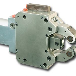
FRUN steady rests are used for all standard applications with mounting dimensions similar to the FRU Series Steady Rests.
FRUN steady rests are used for all standard applications with mounting dimensions similar to the FRU Series Steady Rests. The compact size allows for easy mounting on flat or slant bed lathes. Mounting brackets can be supplied to meet your needs. All Kitagawa-NorthTech steady rest models come with a spare set of rollers and spare chip guard.
STANDARD FEATURES
- Fully sealed body
- Safety valve
- Provision for max. opening feedback
- 1 set swarf guard 3-piece
- Provision for compressed air connection
- Provision for centralized lubrication
(Click image for larger view)
| Steady Rest Type | FRUN1 | FRUN2 | FRUN3 | FRUN3.1 | FRUN3.2 | FRUN4 | FRUN5 | FRUN5.1 | |
| A | 214.5 | 277 | 428 | 436 | 451 | 603 | 697 | 717 | |
| B | 149 | 195 | 312 | 320 | 335 | 448 | 510 | 530 | |
| C | 52 | 70 | 115 | 123 | 138 | 146 | 178 | 198 | |
| D | 66 | 85 | 135 | 135 | 135 | 240 | 270 | 270 | |
| E | 140 | 170 | 262 | 262 | 262 | 365 | 400 | 270 | |
| F | 160 | 195 | 295 | 295 | 295 | 405 | 440 | 440 | |
| G | 63 | 75 | 95 | 95 | 95 | 110 | 145 | 145 | |
| K | 28 | 35 | 45 | 45 | 45 | 60 | 75 | 75 | |
| L | 15 | 19 | 25 | 25 | 25 | 25 | 29 | 29 | |
| M | 24 | 35 | 47 | 47 | 47 | 52 | 62 | 62 | |
| 0 | 65.5 | 82 | 116 | 116 | 116 | 155 | 187 | 187 | |
| P1 | 95.5 | 122 | 144 | 144 | 144 | 164 | 174 | 174 | |
| P2 | 37.5 | 61 | 72 | 72 | 72 | 82 | 87 | 87 | |
| P3 | 58 | 61 | 72 | 72 | 72 | 82 | 87 | 87 | |
| R | 55 | 65.5 | 115.5 | 124 | 140 | 172 | 209 | 229 | |
| S | 11 | 14 | 18 | 18 | 18 | 23 | 23 | 23 | |
| T | 57 | 69 | 93 | 93 | 93 | 108 | 140 | 140 | |
| T1 | 62 | 74 | 98 | 98 | 98 | 113 | 147 | 147 | |
| V | 41 | 51 | 85 | 93 | 108 | 128 | 160 | 180 | |
| W2 | 5 | 11.2 | 10 | 10 | 10 | 18.3 | 19 | 19 | |
| W3 | 20 | 30 | 50 | 50 | 50 | 58 | 62 | 62 | |
| β | 45 | 30 | 30 | 30 | 30 | 40 | 40 | 40 | |
| α | 15 | 15 | 15 | 15 | 15 | 15 | 18 | 18 | |
| Centering range | U1 | 6 | 8 | 12 | 20 | 50 | 30 | 45 | 85 |
| U2 | 70 | 101 | 152 | 165 | 200 | 245 | 310 | 350 | |
| Max. axial opening | U3 | 75 | 106 | 162 | 170 | 202 | 253 | 318 | 352 |
| Cylinder bore | d (dia) | 30 | 50 | 70 | 70 | 70 | 90 | 100 | 100 |
| Hydraulic connection | h | 1/8″ BSP | G 1/4″ | G 1/4″ | G 1/4″ | G 1/4″ | G 1/4″ | G 1/4″ | G 1/4″ |
| Operating pressure min(max) | bar | 6(50) | 8(70) | 8(80) | 8(80) | 8(80) | 8(80) | 8(80) | 8(80) |
| Max clamp force | daN | 100 | 450 | 1000 | 1000 | 1000 | 1700 | 2000 | 2000 |
| Centering accuracy | mm | 0.02 | 0.02 | 0.04 | 0.04 | 0.04 | 0.04 | 0.06 | 0.06 |
| Repeatability | mm | 0.005 | 0.005 | 0.007 | 0.007 | 0.007 | 0.007 | 0.01 | 0.01 |
| Max peripheral speed | m/min | 850 | 800 | 725 | 725 | 725 | 725 | 700 | 700 |
| Approx weight | kg | 10 | 20 | 48 | 48 | 48 | 104 | 174 | 178 |


