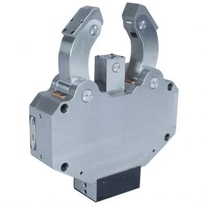
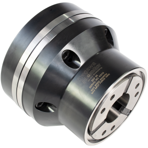
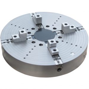
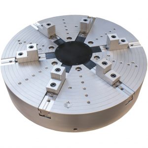
The KRGU Grinding Work Rests Series with retractable body is designed to accommodate the maximum eccentric throw and journal diameter of crank shafts.
The KRGU Grinding Steady Rests Series with retactable body is designed to accomodate the maximum eccentric throw and journal diameter of crank shafts.
STANDARD FEATURES
- Retractable body using guide ways
- Suitable for all crank shaft, cam shaft and cylindrical grinding applications where high eccentric load is a requirement
- High accuracy, with three-point finely adjustable centering capability
- Modular regrindable Carbide or relappable PCD work rest pads
(Click image for larger view)
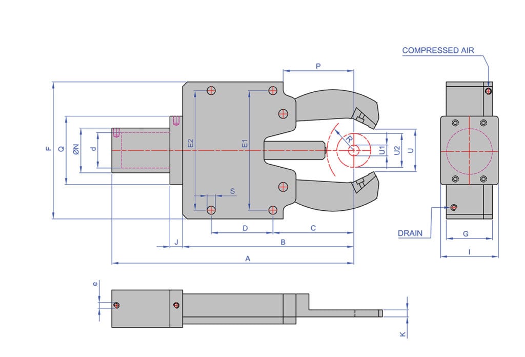
| Steady Rest Type | KRGHS790 | KRGU1517 | KRGU4510 | KRGHS9585 | KRGU502 | KRGU580 | KRGU1019 | |
| Standard Features:
• Safety Valve • Provision for max. opening feedback • 1 set swarf guard 3-piece • Provision for compressed air connection • Provision for centralized lubrication |
A | 420 | 518.5 | 465 | 590.5 | 508.5 | 565.5 | 502 |
| B | 323 | 423 | 358 | 444 | 405 | 462 | 355.5 | |
| C | 190 | 230 | 165 | 254 | 236 | 293 | 162 | |
| D | 90 | 135 | 135 | 142 | 125 | 125 | 135 | |
| E1 | 202 | 262 | 262 | 350 | 337 | 234 | 262 | |
| E2 | 202 | 262 | 262 | 320 | 337 | 234 | 262 | |
| F | 234 | 290 | 290 | 400 | 363 | 260 | 290 | |
| G | 55 | 64 | 57 | 64 | 62 | 62 | 64 | |
| I | 62 | 68 | 68 | 72 | 68 | 68 | 72 | |
| J | 25 | 33 | 33 | 25 | 33 | 33 | 25 | |
| K | 10 | 16 | 10 | 21 | 10 | 12 | 24 | |
| N | 53 | 105 | 119 | 95 | – | 105 | 95 | |
| P | 158.4 | 206.4 | 141.5 | 194.5 | 206.8 | 268.4 | 133.4 | |
| Q | 96 | 141 | 148 | 130 | 141 | 141 | 130 | |
| S | M12 X 1.75 | 14 | 18 | 18 | 22/14 | 20/14 | 18 | |
| U1 | 70 | 150 | 45 | 95 | 50 | 50 | 100 | |
| Clamping Ranges | U2 | 90 | 170 | 105 | 185 | 102 | 80 | 190 |
| Max. axial opening | U | 98 | 181 | 125 | 210 | 109 | 106.5 | 226 |
| Eccentric throw ( R value ) | R | 120 | 122 | 125 | 286 | 205 | 205 | 175 |
| Cylinder bore. | d | 40 | 50 | 50 | 60 | 50 | 50 | 60 |
| Hyd. Connection (BSP) | e | 1/4” | 1/4” | 1/4” | 1/4” | 1/4” | 1/4” | 1/4” |
| Standard operating pressure | bar | 4-15 | 6-30 | 6-30 | 12-45 | 6-30 | 6-30 | 12-45 |
| Max. operating pressure | bar | 20 | 35 | 35 | 60 | 35 | 35 | 60 |
| Max. clamp force/pad. | daN | 60 | 196 | 196 | 425 | 196 | 196 | 425 |
| Centering accuracy over the whole clamping range. | mm | 0.005 | 0.01 | 0.01 | 0.01 | 0.01 | 0.01 | 0.01 |
| Repeatality | mm | 0.002 | 0.004 | 0.004 | 0.004 | 0.002 | 0.004 | 0.004 |


