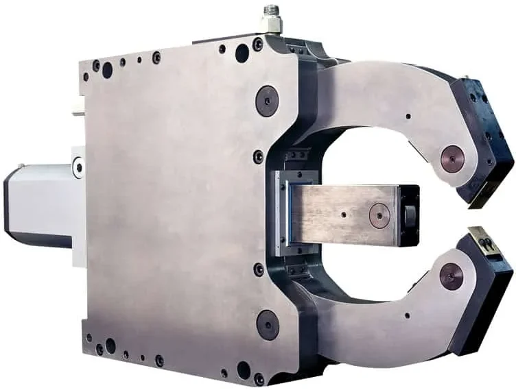
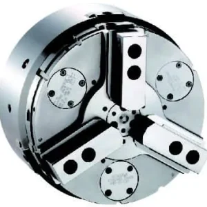
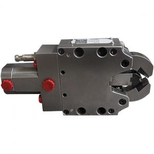
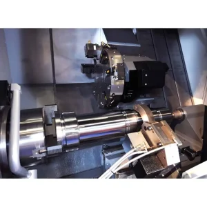
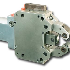
KRHS is designed for crankshaft machining.
The KRHS Series is a steady rest designed for crankshaft machining. Kitagawa-NorthTech can supply a full range of steady rests for crankshaft applications from automotive to heavy railway and marine.
STANDARD FEATURES
- Safety valve
- Provision for max. opening feedback
- Spare set of chip guards
- Spare set of rollers
- Provision for compressed air connection
- Provision for centralized lubrication
- Optional: Provision for coolant flush
(Click image for larger view)
| Steady Rest Type | KRHS 315P | KRHS 520D | KRHS 528C | KRHS 839 | KRHS 222 | KRHS 422 | KRHS 429 | KRHS 419 | KRHS 520K | |
| A | 503 | 620.5 | 730 | 804 | 279 | 621 | 621 | 621 | 613.5 | |
| B | 331 | 442 | 515 | 595 | 189 | 437 | 437 | 437 | 442 | |
| C | 138 | 180 | 178 | 255 | 70 | 146 | 146 | 146 | 180 | |
| D | 135 | 210 | 270 | 270 | 85 | 240 | 240 | 240 | 210 | |
| E | 266 | 330 | 400 | 400 | 170 | 365 | 365 | 365 | 330 | |
| F | 300 | 370 | 450 | 440 | 190 | 400 | 400 | 400 | 370 | |
| G | 80 | 67 | 102 | 110 | 57 | 79 | 79 | 79 | 70 | |
| I | 100 | 118 | 102 | 108 | 69 | 72 | 72 | 72 | 100 | |
| J | 31 | 40 | 40 | 37 | —- | 33 | 33 | 33 | 31 | |
| K | 22 | 26 | 32 | 40 | 22 | 22 | 29 | 19 | 29 | |
| L | 14 | 16 | 20 | 20 | 12 | 13 | 16 | 10 | 18 | |
| M | 35 | 40 | 62 | 62 | 35 | 52 | 52 | 52 | 52 | |
| N (dia) | 132 | 132 | 147 | 137 | —- | 122 | 122 | 122 | 132 | |
| P | 114.5 | 160 | 160 | 216.5 | 58.5 | 128 | 128 | 128 | 160 | |
| Q | 160.5 | 196 | 186 | 184 | 124 | 162 | 162 | 162 | 160.5 | |
| r | 139.5 | 187.5 | 209 | 252 | 73 | 172 | 172 | 172 | 187.5 | |
| S | 18 | 20 | 23 | 23 | 14 | 23 | 23 | 23 | 20 | |
| T | 113 | 170 | 183 | 227 | 57.5 | —- | —- | —- | 170 | |
| T1 | 25 | 27 | 32 | 23 | 17 | —- | —- | —- | 27 | |
| T2 | 25 | 27 | 32 | 23 | 17 | —- | —- | —- | 27 | |
| Clamping range without chip guard | U1 | 40 | 45 | 70 | 80 | 8 | 30 | 30 | 30 | 50 |
| U2 | 85 | 100 | 150 | 200 | 101 | 245 | 245 | 245 | 100 | |
| Max. axial opening | U | 220 | 236 | 322 | 402 | 105 | 260 | 260 | 260 | 212 |
| Clamping range with 3 piece chip guard | U1 | 40 | 45 | 70 | 80 | 8 | 30 | 30 | 30 | 50 |
| U2 | 85 | 100 | 150 | 200 | 101 | 245 | 245 | 245 | 100 | |
| Max. axial opening | U | 220 | 236 | 322 | 393 | 105 | 260 | 260 | 260 | 212 |
| Eccentric throw | R | 110 | 120 | 155 | 195 | 55 | 127 | 127 | 127 | 108.2 |
| Cylinder bore | d (dia) | 80 | 80 | 80 | 80 | 50 | 60 | 60 | 60 | 80 |
| Hydraulic connection (BSP) | e | 1/4″ | 1/4″ | 1/4″ | 3/8″ | 1/4″ | 1/4″ | 1/4″ | 1/4″ | 1/4″ |
| Lubrication ports | g | M8X1 | M8X1 | M10X1 | M10X1 | 1/8″ | 1/8″ | 1/8″ | 1/8″ | 1/8″ |
| Standard operating pressure | bar | 5(30) | 5(40) | 5(55) | 5(55) | 5(70) | 6(50) | 6(50) | 6(50) | 1(40) |
| Max. operating pressure | bar | 35 | 45 | 60 | 60 | 70 | 55 | 55 | 55 | 55 |
| Max clamp force/roller | daN | 500 | 1000 | 1400 | 1400 | 450 | 470 | 470 | 470 | 830 |
| Clamping pressure/roller at 6 bar | daN | 100 | 100 | 100 | 100 | 45 | 56 | 56 | 56 | 100 |
| Centering accuracy over entire clamping range | mm | 0.04 | 0.05 | 0.05 | 0.05 | 0.02 | 0.04 | 0.04 | 0.04 | 0.05 |
| Repeatability | mm | 0.01 | 0.01 | 0.01 | 0.01 | 0.005 | 0.01 | 0.01 | 0.01 | 0.01 |
| Max peripheral speed | m/min | 500 | 525 | 350 | 350 | 920 | 720 | 720 | 720 | 720 |
| Approx weight | kg | 50 | 70 | 150 | 190 | 18.5 | 86 | 86 | 86 | 80 |

