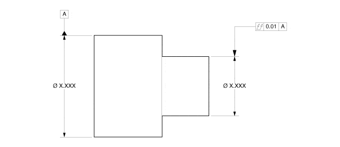
TOTAL RUNOUT (TOHT-L • RUHN-OUT)
DEFINITION: A COMPOSITE CONTROL OF ALL SURFACE ELEMENTS. THE TOLERANCE APPLIED SIMULTANEOUSLY TO CIRCULAR AND LONGITUDINAL ELEMENTS AS THE PART IS ROTATED 360 DEGREES. TOTAL RUNOUT CONTROLS CUMULATIVE VARIATION OF CIRCULARITY, STRAIGHTNESS, COAXIALITY, ANGULARITY, TAPER, AND PROFILE WHEN IT IS APPLIED TO SURFACES CONSTRUCTED AROUND A DATUM AXIS. WHEN IT IS APPLIED TO SURFACES CONSTRUCTED AT RIGHT ANGLES TO A DATUM AXIS, IT CONTROLS VARIATIONS OF FLATNESS AND PERPENDICULARITY.
As stated here above, total run-out is a composite control. As such, the result is the accumulation of:
- Circularity
- Straightness
- Coaxiality
- Angularity
- Taper
- Profile
It should be noted that while the definition includes all of these, it does not necessarily mean that every scrap part is the cause of more than just one. Whether it is determined that you are struggling with one or all six, workholding has a direct impact towards getting total runout under control.
Workholding performs two basic functions:
- Positions the part appropriately
- Grips the part sufficiently to resist part movement against cutting forces.
If point #1 is performed appropriately, then it can be argued that the source of continued error would need to be located elsewhere (i.e., head stock alignment, turret alignment, etc.).
If point #1 is not appropriate to the application, then how might workholding be contributing to the error? How might the product be to blame? What principles need to be considered?
If we were to assume the work piece were a round cylinder, then we would want to be sure that this same cylinder’s axis perfectly shared the same axis as that of rotation (i.e., lathe application). If this basic requirement wasn’t satisfied, then the last 5 controls above would be in put in jeopardy.
In practical terms, what can cause this to happen?
- Jaw forming techniques
- Jaw “lifting”
- Worn chuck
- The run-out tolerance is tighter than the chuck accuracy
- Short gripping length relative to diameter ratio
- Maintenance
Jaw Forming
Without going into the fundamentals of how soft jaws are formed (i.e., machined), we can describe some of the more popular effects when done so improperly. These would include: jaws having positive or negative tapers from front to back (or back to front), poor surface finish altering the jaws centerline, the centerline being offset by not pre-loading the jaws correctly or in the correct direction.
Short gripping length to diameter ratio (L:D)
A steel washer might be an excellent example of this. Its length (thickness) is just too short for a workholding devise to establish its centerline by. If we were to grip it 10 times, the chuck would attempt to establish a unique centerline with each attempt, and they would still all be incorrect.
What is the solution?
If one of its faces were perpendicular to the outer diameter in such a way as to be used as a surrogate for the outer diameter, we could then use the face rather than the outer diameter (OD). Since it would be imperative to keep this face back against this surface, “jaw lift” would need to be taken out of the equation.
Jaw Lift – as it relates to gripping poor L:D (ratio) parts
All conventional sliding jaw chucks experience a measure of jaw “lift.” There are 4 primary reasons:
-
- The clearance between the master jaw and that of the body. Thus the phrase “sliding jaw” speaks to this engineered clearance.
- Due to wear this same clearance has increased over time.
- Chuck body flex
- Hydraulic pressure is too high for the jaw height being used.
WHERE DOES THIS LEAVE US?
The earlier described part stop (i.e., locator) still offers us the qualified surface needed, but the chuck, rather than lifting the part away from the part stop, must instead pull the part back against this surface. Only then have we built robustness into the process via the workholding.

