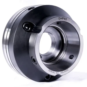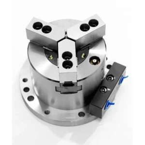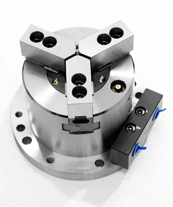
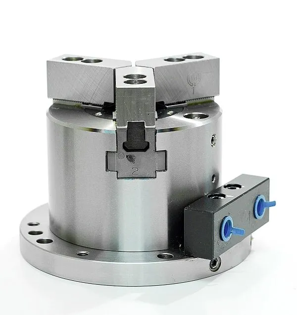
Low profile, lightweight design using a self-contained air cylinder that requires only piping for air.
This low profile, lightweight design uses a self-contained air cylinder which only requires piping for air. Quick installation for drilling machines or machining centers. High gripping force and concentricity from wedge actuated jaws. Thru-hole available for part component entry or for design of rear air blast for chip (or swarf) removal. New extended working range. Optional lock valve unit allows the chuck to be used as clamping unit without need for continuous air feed supply.
ADVANTAGES
- Functionally flexible
- High gripping force
- Low profile, lightweight design
- Thru-hole
- Quick and easy installation
- Uses standard soft or hard jaws
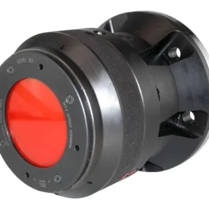
LV-2 AIR LOCK VALVE OPTION
Maintains pressure if loss of supply occurs.
SPECIFICATIONS
| MODEL | UNIT | AS04 | AS06 | AS08 | AS10 | AT04 | AT06 | AT08 | AT10 |
| Jaw Stroke (Diameter) |
in. | 0.205 | 0.205 | 0.248 | 0.248 | 0.205 | 0.205 | 0.248 | 0.248 |
| Gripping Force (85 psi) |
lb. | 1683 | 4708 | 7403 | 10769 | 1683 | 4708 | 7403 | 10769 |
| Weight with Soft Blank Top Jaws |
lb. | 16 | 35 | 61 | 94 | 15 | 33 | 59 | 90 |
| Max. Operation Pressure |
psi | 100 | 100 | 100 | 100 | 85 | 85 | 85 | 85 |
| Matching Soft Top Jaw |
SB04B1 | SB06B1 | SB08B1 | SB10A1 | SB04B1 | SB06B1 | SB08B1 | SB10A1 | |
| Gripping Diameter |
max. in. | 4.331 | 6.496 | 8.268 | 10.000 | 4.331 | 6.496 | 8.268 | 10.00 |
| min. in. | 0.394 | 0.906 | 1.181 | 1.969 | 0.394 | 0.906 | 1.181 | 1.969 | |
| Dia. A | in. | 5.827 | 7.992 | 9.764 | 11.811 | 5.827 | 7.992 | 9.764 | 11.811 |
| Dia. B | in. | 4.331 | 6.496 | 8.268 | 10.000 | 4.331 | 6.496 | 8.268 | 10.000 |
| Dia. C (H7) | in. | 0.787 | 0.984 | 1.417 | 1.969 | 0.984 | 1.417 | 1.969 | |
| Dia. D | in. | 0.787 | 1.181 | 1.693 | 0.787 | 1.181 | 1.693 | ||
| E | in. | 3.543 | 3.740 | 4.173 | 4.331 | 3.543 | 3.740 | 4.173 | 4.331 |
| F | in. | 0.591 | 0.591 | 0.591 | 0.630 | 0.591 | 0.591 | 0.591 | 0.630 |
| G* | in. | 2.972 | 4.055 | 4.941 | 5.807 | 2.972 | 4.055 | 4.941 | 5.807 |
| in. | (4.350) | (5.433) | (6.319) | (7.185) | (4.350) | (5.433) | (6.319) | (7.185) | |
| H | in. | 1.063 | 1.417 | 1.654 | 1.811 | 1.063 | 1.417 | 1.654 | 1.811 |
| J | in. | 2.165 | 2.835 | 3.740 | 4.331 | 2.165 | 2.835 | 3.740 | 4.331 |
| K | in. | 0.906 | 1.220 | 1.378 | 1.575 | 0.906 | 1.220 | 1.378 | 1.575 |
| Dia. L | in. | 5.118 | 7.283 | 9.055 | 11.024 | 5.118 | 7.283 | 9.055 | 11.024 |
| Dia. M | in. | 0.354 | 0.433 | 0.433 | 0.512 | 0.354 | 0.433 | 0.433 | 0.512 |
| N | in. | M8 | M8 | M10 | M8 | M8 | M10 | ||
| P | in. | 2.165 | 2.677 | 3.346 | 2.165 | 2.677 | 3.346 | ||
| Q | in. | 0.709 | 0.984 | 1.181 | 0.709 | 0.984 | 1.181 | ||
| R | in. | 1.693 | 2.756 | 3.543 | 4.331 | 1.693 | 2.756 | 3.543 | 4.331 |
| S | in. | 1.299 | 1.299 | 1.299 | 1.299 | 1.299 | 1.299 | 1.299 | 1.299 |
| T | in. | 1.339 | 2.362 | 3.150 | 3.740 | 1.339 | 2.362 | 3.150 | 3.740 |
| U | in. | 0.591 | 0.591 | 0.591 | 0.591 | 0.591 | 0.591 | 0.591 | 0.591 |
*Dimension within ( ) includes air lock
valve (optional).
AS DIMENSIONAL DRAWINGS
AT DIMENSIONAL DRAWINGS